Lab 5: Interrupts
Introduction
In this lab, hardware interrupts were configured on the STM32L432KC to capture all transitions from a quadrature encoder and accurately report the angular velocity of a motor. A DC motor with an attached quadrature (Hall-effect) encoder was powered and wired to the MCU’s GPIO pins. Interrupts were enabled and configured via register programming and an interrupt service routine (ISR) written in C. The interrupt inputs were decoded using a scheme that accounts for rotation direction and potential debouncing or jitter (as described in the STM32L4 reference manual), producing a signed pulse count from the encoder channels. The decoded pulse count was sampled and reset every 100 ms, yielding a velocity estimate at 10 Hz.
Design and Testing Methodology
Work began with a review of quadrature encoder operation to determine how best to detect direction and maximize measurement resolution. To obtain the most precise velocity estimate, the design detects encoder pulses on both rising and falling edges of both channels A and B, i.e., four edges per mechanical cycle. With the implemented configurations, the Nested Vector Interrupt Controller (NVIC) redirects any encoder edge to the appropriate ISR by saving the program counter and loading the ISR address into the PC. The ISRs themselves are intentionally short, only setting a flag and then returning. The main loop in main.c detects these flags, reads both GPIO pins, and performs the decoding and accumulation of pulses. The decoding logic is inspired by the TIM2 Encoder Interface Mode documented in the STM32L4 reference manual. From there, the velocity is calculated following the equation:
\[ Velocity = \frac{pulses * time}{1000*no.edges*PPR} \]
As time is reported in milliseconds, the factor of time/1000 component converts to seconds in the denominator. The sampling interval is 100ms and the encoder has a PPER of 408 Pulses Per Revolution. The code is written in a modular way such that switching to a report frequency of 1 Hz is simple and easy.
Technical Documentation
The basis for encoding of detected pulses was taken from the STM32L4xxxx Reference manual. The diagram is shown below.
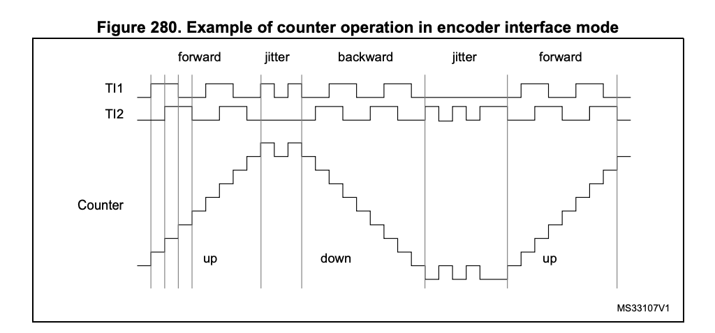
Each current and previous value was recorded, and the resulting contribution to the total number of pulses derived. To do so, the following two tables were written out.
Previous and Current Encoder Values
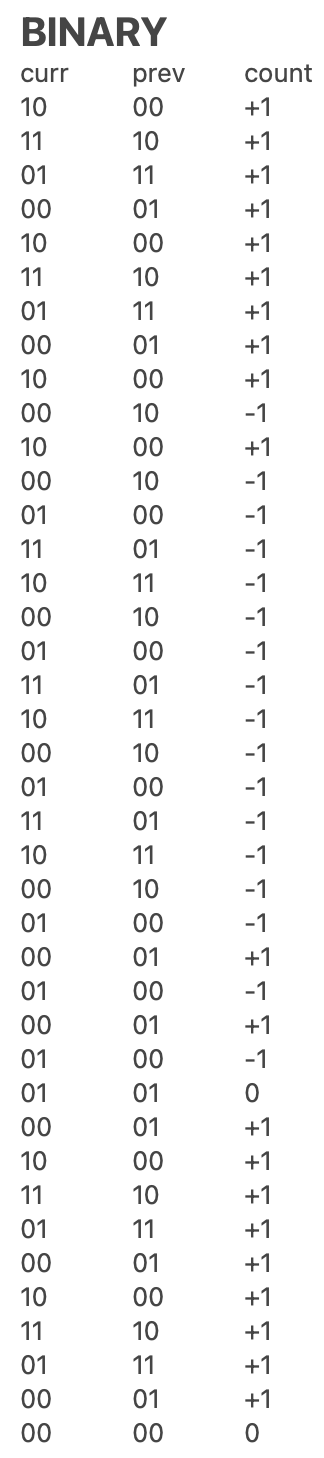

These detailed processing was executed through a case statement in C.
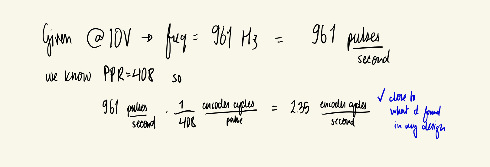
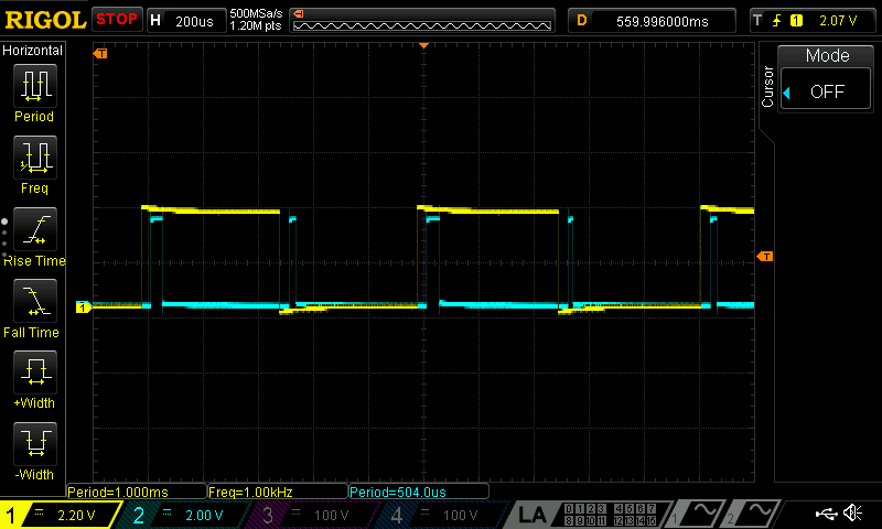
To validate the implementation, the encoder pulse frequency was measured on an oscilloscope. The corresponding motor velocity was computed by hand from the measured frequency and compared to the velocity computed and displayed via the MCU in SEGGER. The results matched within the expected tolerance.
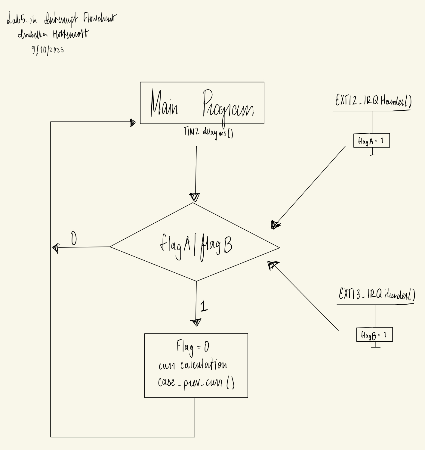
Interrupt Diagram
The below diagram illustrates the main steps of the program and different function calls that execute with the enabled interrupts.
Schematic
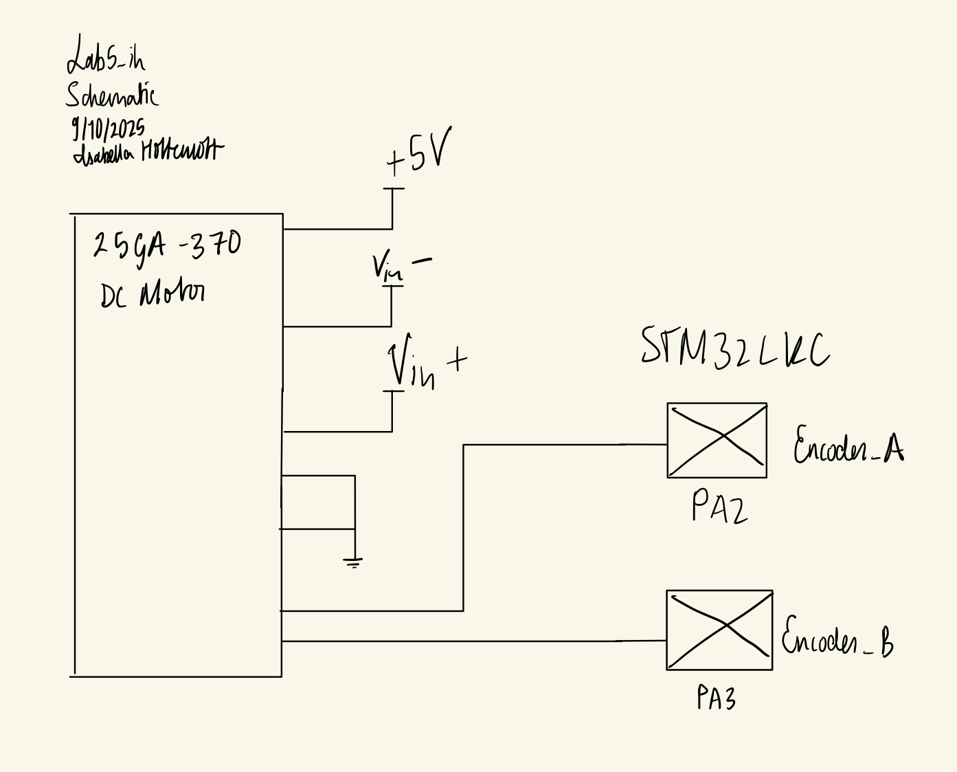
The below schematic illustrates the simple setup for this design.
Results and Discussion
This project successfully demonstrated the responsiveness and accuracy achievable with an interrupt-based interface to a quadrature encoder.
To quantify the benefit of interrupts, a second version of the code was implemented using polling: the GPIO pins were periodically sampled in software with a 200 ms delay. The two approaches were compared on an oscilloscope:
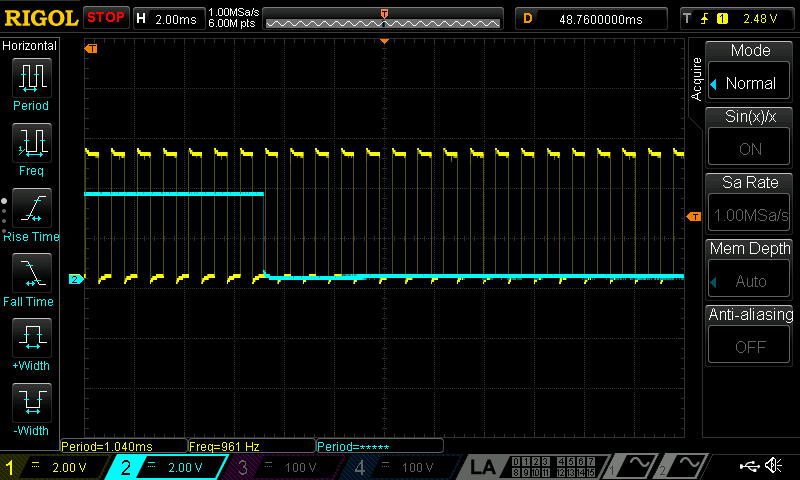
Polling Oscilloscope Traces
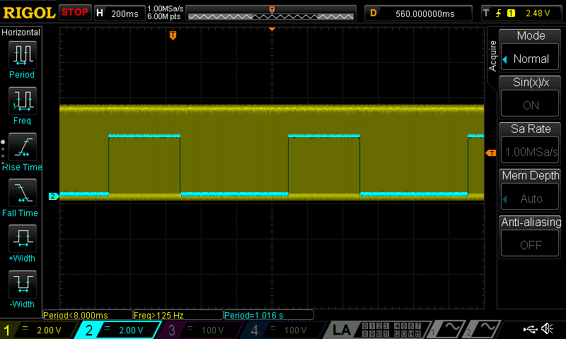
Interrupt Oscilloscope Traces
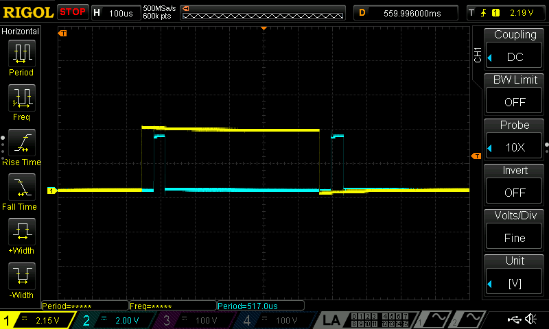
With the polling approach (200 ms delay), the MCU missed a large fraction of the encoder pulses. As a result, the velocity estimate was significantly underestimated, especially at higher motor speeds. With the interrupt-based approach, both the rising and falling edges of each encoder pulse were captured. The measured latency from an encoder edge to the “acknowledge” toggle was approximately 40 uS for the interrupt approach. Therefore, the maximum frequency of pulses that the encoder can report is 24.5 kHz. Using the polling approach, my encoder delays 200ms, so the maximum frequency of pulses is 5 Hz.
Conclusion
This design successfully implemented a quadrature encoder interface on the STM32L432KC using external interrupts. The reported velocity is precise for several reasons:
- The system responds quickly to edges due to the interrupt-based design.
- Both channels and both edges are used, providing high effective resolution.
- The 10 Hz update rate strikes a good balance between responsiveness and stability.
- Velocity is computed with sufficient precision to capture small changes in speed.
Together, these choices yielded an accurate measurement of motor angular velocity and highlighted the advantages of interrupts over simple polling in embedded systems.
AI Prototype Summary
I prompted ChatGPT5 with the following: “Write me interrupt handlers to interface with a quadrature encoder. I’m using the STM32L432KC, what pins should I connect the encoder to in order to allow it to easily trigger the interrupts?”
The LLM’s response, as well as my evaluation of the response, can be found here