Lab 4: Digital Audio
Introduction
In this lab, two general-purpose timers on the STM32L432KC board were used to generate square waves at specified frequencies and play Beethoven’s Für Elise over a GPIO pin. This required understanding and configuring several on-chip peripherals using the STM32L432KC reference manual and datasheet. In addition, a low-voltage audio amplifier circuit was assembled to drive a Jameco 8 Ω speaker and provide volume control.
Design and Testing Methodology
The internal clock was first multiplied using the PLL to obtain an 80 MHz system clock. This 80 MHz clock was then selected as the system clock source and routed onto the APB2 and AHB2 buses so that both the timers and GPIO peripherals could access it. Two general-purpose timers were used: TIM15 for frequency generation and TIM16 for note duration timing. Both timers were configured using the relationship between the prescaler (PSC), auto-reload register (ARR), and timer input clock.
\[ Fdesired = \frac{Ftim}{(2*(PSC + 1)*(ARR + 1))} \]
and
\[ Durdesired = \frac{(4*(PSC + 1)*(ARR + 1))}{Ftim} \]
A C for loop iterated through an array of pitch–duration pairs encoding the score for Für Elise. For each entry: * TIM15 set the output frequency and toggled a GPIO pin at the desired note pitch. * TIM16 measured the corresponding note duration.
Both behaviors were driven by the update interrupt flag in the timers’ status registers (SR).
The following desmos sheet was used to verify the frequencies of the Timer 15 are correct.
The following desmos sheet was used to verify the durations of the Timer 16 are correct.
Two helper functions, set_hz() and config_delay(), encapsulated the frequency and duration configuration logic. These functions were called from within the main for loop in main.c.
The GPIO bank B was initialized to toggle pin 6 for audio output.
Technical Documentation
After analyzing the reference manual and understanding what was required for this design, the following registers were configured.
FLASH: ACR RCC: CR, PLLCFGR, CFGR, APB2ENR, AHB2ENR GPIO: MODER, ODC TIM15: PSC, EGR, CR1, ARR, SR, CNT TIM16: PSC, EGR, CR1, ARR, SR, CNT
The below calculations were used to determine an appropriate prescaler and auto-reload-register value:
The values for the PSC and ARR registers were selected using the considerations below.
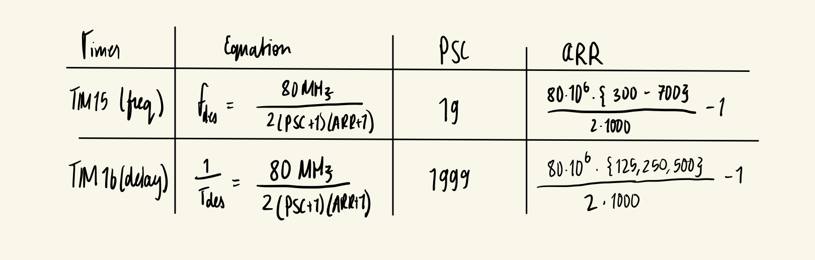
TIM16: A prescaler of 1\2000 was selected, so PSC was loaded with 1999. ARR values for the required note durations were computed at runtime inside config_delay() and verified using desmos sheet.
TIM 15: A prescaler of 20 was selected, so PSC was loaded with 19. ARR values for the required note frequencies were computed at runtime inside set_hz() and verified using desmos sheet.
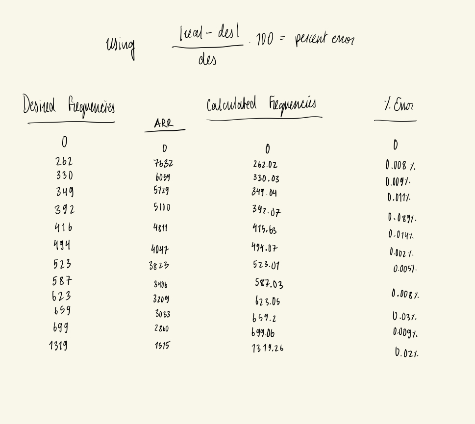
These values are proven to fall within 1% of the desired frequencies. The ARR values of the register were recorded over the Segger Registers window. These were used to derive the resulting frequency of the output signal. Calculations can be found using the following desmos. All unique notes were tested.
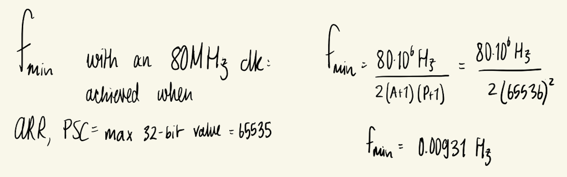
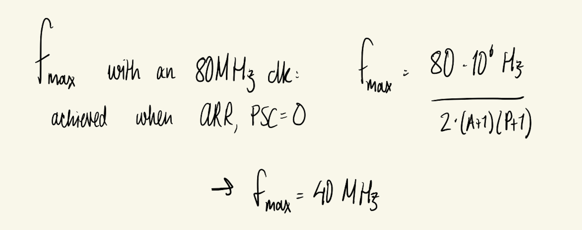
From these settings, the minimum and maximum achievable frequencies were derived:
In addition to Für Elise, a short custom composition playing a German Happy Birthday song was written. The following fixed 2D array of frequencies and durations was written.
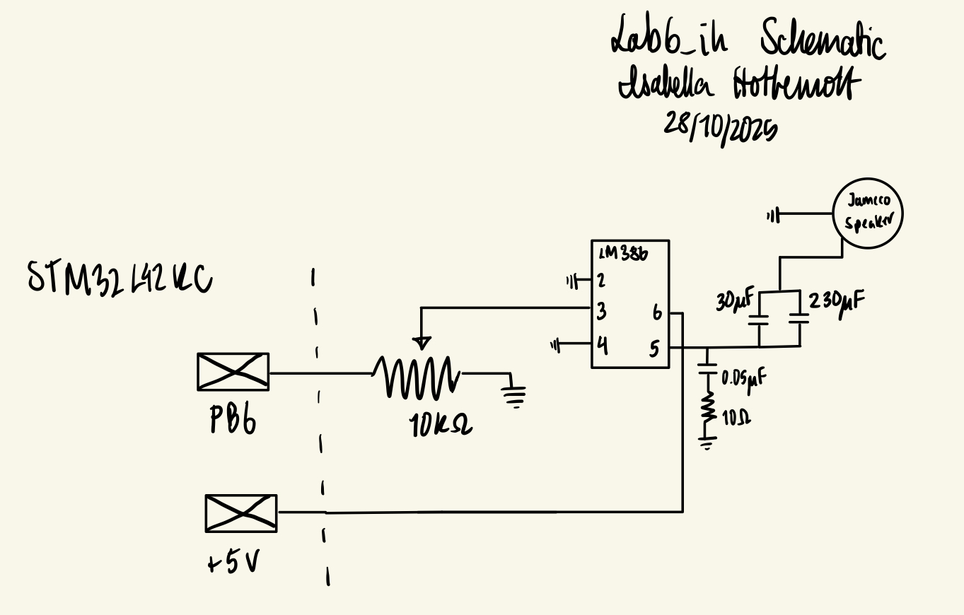
Schematic
The audio amplifier circuit followed the recommended configuration from the LM386 datasheet. The following schematic was implemented in hardware.
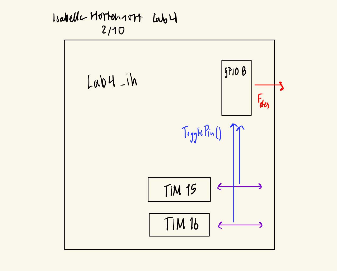
Block Diagram
An abstracted block diagram of the overall system is shown below:
Results and Discussion
The design successfully generated the pitches and durations required to assemble Für Elise from individual notes. The audio amplifier circuit was compact, straightforward to assemble, and produced a clearly audible output on the 8 Ω speaker. For the modest frequency range used in this lab, the chosen timer configuration and GPIO toggling approach were simple, reliable, and did not introduce noticeable timing issues, so I decided to pursue this design.
Conclusion
This project provided hands-on experience with the STM32L432KC’s clock tree, general-purpose timers, GPIO configuration, and the process of navigating the reference manual and datasheet. It also offered a creative opportunity to implement and parameterize musical pieces—both a classical work and a custom composition—using low-level embedded C and on-chip peripherals.
AI Prototype Summary
I provided the LLM with: “What timers should I use on the STM32L432KC to generate frequencies ranging from 220Hz to 1kHz? What’s the best choice of timer if I want to easily connect it to a GPIO pin? What formulae are relevant, and what registers need to be set to configure them properly?””
The LLM’s response, as well as my evaluation of the response, can be found here